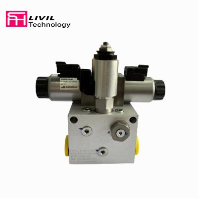
Knowledge and Function of Hydraulic Valve
Key points of knowledge about hydraulic valves
(1) One-way valve
1. Ordinary one-way valves only allow oil in one direction to pass through, and block the flow in the other direction. The control port of the one-way valve is connected to high-pressure oil, which can flow in the opposite direction. However, it should be noted that when the control oil port is not working, it must be connected to the oil tank, otherwise it will be difficult to reset.
2. When the one-way valve is used to control the opening and closing of the oil circuit, the opening pressure is 0. 03- 0. 0 SMPa, and when used as a back pressure valve, the opening pressure is 0.4 MPa.
3. The one-way valve core is a poppet valve or a ball valve, which has good sealing performance. The pressure relationship between the inlet and outlet oil is:
P1=P2+Pk.
1. The "position" of the reversing valve refers to the working state, "pass" - the number of oil pipes. Generally, the valve core is a slide valve.
2. The ways to control the movement of the valve core include: manual, motorized (stroke valve), electromagnetic, hydraulic, and electro-hydraulic. Reset methods also include spring reset, electromagnetic reset, etc.
3. When the reversing valve is in different working positions, the connection method of each oil port is called the function of the slide valve. When the slide valve is in the neutral position, the connection method of each oil port is called the neutral position function of the slide valve. The different neutral functions of each oil port are "0" type neutral functions, and the differential cylinder is a "p" type neutral function, so that the neutral functions of pump unloading are "H", "M", " K" type median function.
4. The electro-hydraulic reversing valve is composed of a hydraulic valve and an electromagnetic reversing valve. Due to the limited electromagnetic suction force, electro-hydraulic directional valves must be used for large flow valves with large hydraulic power (C > 100 L/min). To push the electro-hydraulic reversing valve to change direction, a pressure of 0.4 MPa is required.
5. The reversing valve should understand its reversing reliability, pressure loss, internal leakage, etc.
6. It should be noted that the reversing valve is connected to the oil circuit in the neutral position or normal position. When the electromagnet is energized, it works close to the working state of the electromagnet. Do not make a mistake.
(3) Relief valve
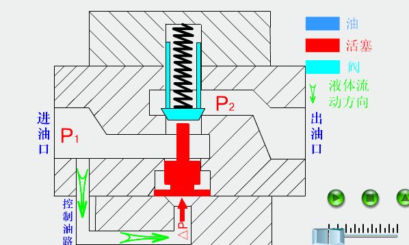
1. The relief valve is normally closed and is controlled to open by the pressure of the inlet pressure oil. Since the spring chamber of the relief valve is connected to the oil outlet (internal leakage), the pressure required to open the relief valve is: P1=P2+Pk
2. When working, the relief valve is normally open and used as a pressure stabilizing valve (pressure regulating valve), and when normally closed, it is used as a safety valve. It can also be connected to the oil return line as a back pressure valve. When the pressure at the remote control port of the pilot relief valve is lower than the set pressure, the pressure control valve at the remote control port is opened. The remote control port is connected to the fuel tank as an unloading valve.
3. When studying, pay attention to the working principle of the pilot relief valve. In particular, it is important to understand the role of damping holes. 5% of the oil flows from the pilot valve back to the tank, and 95% of the oil flows back to the tank from the main spool opening.
(4) Sequence valve
1. The shunt valve is normally closed and can be opened by imported pressure oil, which is called internal control. It can also be controlled by other high-pressure oil, which is called external control. The oil in the spring chamber is connected to the outlet for internal leakage, and the outlet pressure oil works, so The spring chamber oil needs to be introduced into the oil tank separately (external leakage). The internal control and internal leakage sequence valve is the same as the relief valve and has the same symbol. It can be said to be a relief valve.
2. Since the oil in the spring chamber needs to be introduced into the oil tank separately, the opening valve will open as long as it is greater than its set pressure Pk. When the valve is opened, the relationship between its inlet pressure and outlet pressure is:
P1 = Max { P2, Pk }
Pl = Pk, the valve opening is constant and satisfies the balance equation. When P1 = P2, the valve opening is fully open.
3. The sequence valve is named because it forms a sequential action circuit. It can also be used as a balance valve and back pressure valve.
1. The rejection valve is normally open and closed by the outlet pressure control valve. The oil in the spring chamber is connected to the oil tank separately. When the outlet pressure exceeds the set pressure of the spring, the valve closes. The relationship between import pressure and export pressure is:
P1=p2=PL
Pl = system pressure
When the load pressure PL < Pk, the load pressure PL is when Pk
P2 = Pk (PL is passive load) P2 = PL (PL is active load)
2. The purpose of the pressure reducing valve is to obtain a lower pressure in the secondary oil circuit than in the main oil circuit, so that one oil source can output several different pressure oils at the same time. It is widely used in clamping mechanisms, lubrication systems and control systems. When the oil source pressure is unstable, a pressure reducing valve can be connected in series in the circuit to obtain a relatively stable and lower pressure.
(6) Throttle valve
1. The throttle valve controls the flow rate by the opening (area) of the valve port. It is a thin-walled small hole type and has nothing to do with the viscosity (oil temperature) of the oil. Pay attention to the calculation of the areas of various throttle valves.
2. The throttle valve regulates the flow through the area, but it cannot stabilize the flow because it is affected by the load. This effect is expressed by the rate of change of load on flow, that is, stiffness. The greater the stiffness, the smaller the impact of load changes on the flow rate.
3. Another indicator of the throttle valve is the minimum stable flow, which means the minimum flow without periodic pulsation.
4. To analyze the flow valve, the flow equation must be used. In fact, the throttle valve also becomes a liquid resistance.
(7) Speed regulating valve
1. The speed regulating valve can adjust the flow or stabilize the flow. You must be familiar with its working principle of stabilizing the flow.
2. The speed regulating valve can have a structure with the pressure reducing valve in front and the throttle valve in the back, or it can have a structure with the throttle valve in the front and the pressure reducing valve in the back. The principles are the same.
3. The speed regulating valve cannot be connected reversely. If it is connected reversely, it will be equivalent to a thousand throttle valves and the flow rate cannot be stabilized.
(8) Proportional valves, cartridge valves, digital valves
1. The proportional valve controls the opening pressure (pressure valve) and flow (proportional flow valve) of the valve through a proportional solenoid, so that the opening pressure or flow rate of the valve is proportional to the input current. It is a low-precision control valve.
2. The cartridge valve is a hydraulically controlled one-way valve, which is suitable for working conditions with large flow and high water base. It mainly separates the signal part from the power part, and can be combined with other valves to form a complex valve system.
3. The digital valve is controlled by a stepper motor, so that the output flow and pressure are proportional to the number of pulses. It is a relatively high-precision control valve.
The function of hydraulic valve
(1) Function of one-way valve
1. Select the direction of liquid flow and flow in the selected direction to form a specific oil circuit.
2. Distinguish between high and low pressure oil to prevent high pressure oil from entering the low pressure system.
3. Installed at the outlet of the pump to prevent the system pressure from suddenly rising and being transmitted back to the hydraulic system, causing damage to the pump components.
4 When the pump stops, the pressure is temporarily maintained.
5. As a back pressure valve.
6. Cooperate with other valves to make them function in one direction.
(2) The function of hydraulic control check valve
1. Keep the pressure up.
2. Used for support of hydraulic cylinders.
3. Realize the locking of the hydraulic cylinder.
4. Large flow displacement.
5. Used as oil filling valve.
6. Combined into a reversing valve.
(3) The function of the relief valve
1 The overflow function cooperates with the throttle valve to adjust the flow.
2.As a safety valve.
3. Used as an unloading valve, pilot type relief valve + two-position two-way reversing valve.
4. Used as a pressure regulating valve, multi-stage pressure regulation and remote pressure regulation.
5. As a back pressure valve.
(4) Function of sequence valve
1. Produce balance.
2. Make multiple actuators operate sequentially.
3. As an unloading valve.
4. As a back pressure valve
5. It can also be used as a relief valve, safety valve, etc.
(5) Function of pressure reducing valve
1. Reduce the output pressure of the hydraulic pump and supply it to the low-pressure oil circuit. Such as control circuits, lubrication systems, clamping, positioning, and indexing devices.
2. Stabilize pressure. The pressure output by the pressure reducing valve is relatively stable to avoid the impact of a pressure oil fluctuation.
3. Different pressure oil can be output according to needs to supply control oil circuit, auxiliary oil circuit, etc.
4. Connect in parallel with the one-way valve to achieve one-way pressure reductio.
5. Connect in series with the throttle valve to achieve constant flow.


